
















Leverage Squat Machine Assembly

RPM Care / Product Assembly
Leverage Squat Machine:Assembly & Setup
Build from the base upwards with the assembly drawing and real-life photographs beside each stage. Keep the illustrated guide close while identifying your parts and their connection points.
Plate-loaded · Drawing reference 5026 · Corrected weight-plate position
Before you begin: Use the supplied fixings and the machine-specific installation specifications. This guide shows component positions; bolt sizes and tightening torques are not specified here. Do not add training plates during assembly.
Machine dimensions & components
RPM lists an overall product size of 215 × 162 × 170 cm, a net weight of 215 kg, a gross weight of 235 kg, and main tube dimensions of 65 × 114 mm. The webpage does not label the dimension order, so confirm length, width and height before planning installation. These are product dimensions, not operating-clearance requirements.
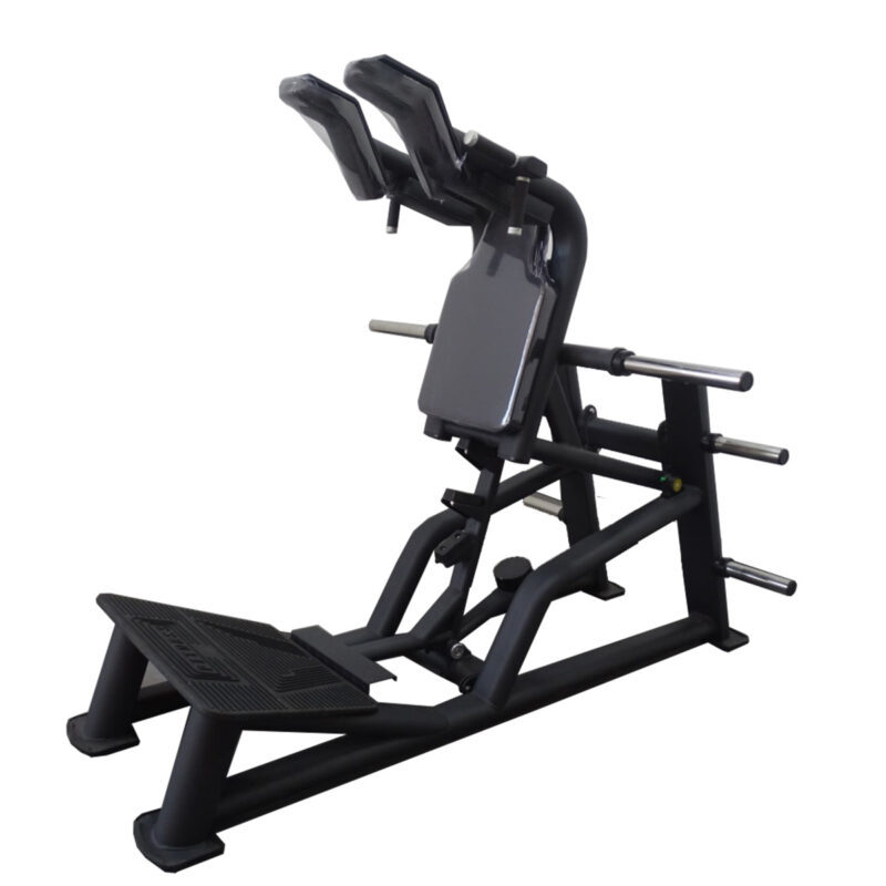
For this guide, front means the end with the large angled footplate. Rear means the end with the tall uprights and storage pegs. Describe left and right while standing at the front and looking towards the rear; this is a guide convention, not a manufacturer part designation.
- A — Stationary side frames:the two long floor-level sides, curved braces, rear uprights and floor-contact feet.
- B — Base connectors:the members that join the side structures, including the transverse lower connection shown separated near the bottom of the drawing.
- C — Upper lever assembly:the moving structure carrying the back pad, shoulder supports and lateral loading sleeves.
- D — Pads and grips:the large rectangular back pad, paired angled shoulder pads and nearby handles. Some are drawn separated from their supports.
- E — Central support/catch assembly:the central lower mechanism beneath the back pad, including several projecting features. The stepped rail and rectangular pedal plate are shown in Figure 9; the operating specifications to obtain are listed in Section 6. The circular weight plate beside this mechanism is positioned beneath its frame bar near the free end, away from the central upright attachment, not on top.
- F — Front footplate assembly:the angled standing surface and its supporting structure at the front.
Plate sleeves versus storage pegs: the photo shows long sleeves associated with the upper moving structure and additional pegs on the stationary rear uprights. Their locations help distinguish likely loading positions from storage positions, but RPM must confirm each peg’s function and limit. Do not load a peg simply because a plate fits it.
Before you start
- Check identity. Check the product label, serial number and carton identifier against the supplied machine documentation before assembly.
- Prepare the location. Establish a level, stable floor and the required access/operating clearance. Given the stated 215 kg net weight, plan safe handling of heavy components and confirm floor and anchoring requirements before installation.
- Lay out parts by group A–F. Photograph the complete layout. Keep packaging labels with their parts and note components already assembled.
- Sort the hardware. Separate bolts by diameter, length and markings; keep washers, spacers, nuts and retaining components distinct. Measurements help request identification but do not prove suitability.
- Obtain the hardware schedule. Match every structural connection and pivot to the supplier’s specification before proceeding. Do not trial-fit random bolts to decide which ones are correct.
- Arrange suitable support. Use assistance and lifting/support equipment appropriate to actual component weights. Do not lift the upper assembly by upholstery or place hands beneath an unsupported lever.
Tools to confirm: correctly sized sockets/spanners, a torque wrench covering the specified tightening range, and any specifically required lifting or retaining-hardware tools. Socket sizes and torque ranges cannot be selected from the drawing alone.
Assembly drawing
The circular weight plate fits underneath the short frame bar near its free end—not on top. Select the drawing to view the full-resolution version.

The large view separates components so their relationships are easier to see. Red dashed lines indicate apparent alignment or attachment paths. They do not specify an assembly order, bolt type or torque.
Assembly stages
Assemble the machine from the base upwards: complete the stationary base and lower frame before installing the upper lever assembly. Read the assembly specifications in Section 6 before starting assembly. At every stage, use the specified fasteners, washers, spacers and retention method. The photographs show an assembled machine; any training plates visible are for reference only. Do not add training plates during assembly.
Assembly / Stage 01
Establish the stationary base
Identify the two side-frame structures and place them in their finished orientation, with the front footplate end facing the intended access direction. Match the lower transverse members and other joining pieces to their visible connection points. Use Figure 4 to match the lower crossmember flange to the side-frame connection.
Checkpoint: both sides have the correct orientation; all base members have been identified; the floor-contact feet are undamaged. Stop if a joint needs force to align or if its hardware cannot be positively identified. Do not enlarge holes or modify parts to make them fit.

Select any photograph to open it at full resolution. Photos show the assembled layout; training plates are reference only.
Assembly / Stage 02
Confirm the front and central lower structure
Identify how the footplate support and central lower members connect to the stationary frame. Some of this area may arrive preassembled. Compare the delivered assembly with the drawing inset and photographs without dismantling factory-built joints unnecessarily. Position the circular weight plate beneath the frame bar near its free end—never on top. Use Figures 3 and 5 for the weight-plate position. Figure 6 shows the underside of the main footplate and its transverse connection. Use the specified mounting hardware and retention method, with each fixing in its designated position.
Checkpoint: the footplate’s orientation agrees with the finished views, and all required lower connections are accounted for. Obtain supplier clarification for obscured joints rather than guessing how they are secured. Check that the plate is secure beneath the bar near its free end and clears the mechanism throughout its prescribed travel.


Select any photograph to open it at full resolution. Photos show the assembled layout; training plates are reference only.
Assembly / Stage 03
Install the supported upper lever
Identify the upper padded lever assembly and its bearing-housing connections at the rear support structures, shown in Figures 7 and 8. Keep it mechanically supported throughout installation. Use the specified axle/bolt arrangement, bearings or bushes, spacers and retaining hardware.
Checkpoint: the prescribed pivot hardware and retention are complete. Do not treat a pivot as an ordinary frame joint or tighten it to an assumed torque. Do not release temporary support until the assembly’s installed support and retention have been verified.


Select any photograph to open it at full resolution. Photos show the assembled layout; training plates are reference only.
Assembly / Stage 04
Verify the support/catch mechanism
Identify the central mechanism below the back pad and its relationship to the upper lever and base. Confirm which feature supports the lever at rest, how it engages/releases and how its settings are selected. Use Figure 9 to identify the stepped central rail, rectangular pedal plate and lower crossmember; the photograph shows their assembled layout, not the release procedure.
Checkpoint: an installer can demonstrate the manufacturer’s specified engagement and release procedure without added plates. Do not assume that any projecting tab is a safe load-bearing stop. If operation is unknown, leave the machine out of service.

Select any photograph to open it at full resolution. Photos show the assembled layout; training plates are reference only.
Assembly / Stage 05
Confirm pads, grips and sleeves
Match the large back pad and paired shoulder pads to their mounting positions. Confirm any grip and sleeve installation required by your delivered version. Identify whether separate pegs are for loading or storage. Figure 10 shows the rear back-pad mounting bars and the visible bolt heads.
Checkpoint: prescribed fixings are present; pads and grips are secure; no loose fitting can obstruct the mechanism. Do not add plates during assembly.

Select any photograph to open it at full resolution. Photos show the assembled layout; training plates are reference only.
Assembly / Stage 06
Complete fastening and commissioning
Apply the specified torques and locking/retention methods. A qualified installer should inspect frame stability, pivot retention, moving-part clearance and the catch/stop mechanism, then carry out the prescribed commissioning procedure.
Checkpoint: missing specifications and unresolved connections have been closed out. An unloaded movement check alone does not prove the machine safe under load.
User setup after commissioning
The machine can be used facing inwards or outwards. These are exercise orientations, not different assembly configurations. Before training, ensure you understand safe entry and exit, body positioning and operation of the support/catch mechanism.
Before each session, check for visible damage, loose fittings, rocking feet, an obstructed platform or a catch that does not engage securely. Do not use the machine if a support, retaining component or safety mechanism is damaged or uncertain.
Start familiarisation with no added plates, under competent supervision after commissioning. The moving structure can still provide substantial resistance; “no added plates” does not mean zero load. Keep hands clear of pivots and moving gaps. Use only the confirmed loading positions and limits, and follow the specified loading arrangement.
Do not attempt to derive effective resistance from plate mass alone: leverage and machine geometry affect the force experienced by the user. No starting resistance or load ratio is stated in the checked product description.
Assembly specifications
Use the machine-specific fastener schedule, tightening torques, pivot-hardware arrangement, load limits and safety-catch instructions. These values and procedures are not specified in this illustrated reference. Use the supplied hardware in its designated locations; do not guess torque values or substitute parts.
Product information: RPM Power Leverage Squat Machine.
Keep the illustrated guide close.
Download the printable guide with the corrected assembly drawing and seven real-life reference photographs.